From Chalk Lines to Laser Precision: Eliminating Manual Layout Errors
From Chalk Lines to Laser Precision: Eliminating Manual Layout Errors
Aerospace and automotive manufacturers still using tape measures and chalk lines for component positioning know the cost of misplaced trust in operator skill. A single miscalculation on a composite fuselage section can trigger $50,000+ in material scrap and schedule delays.
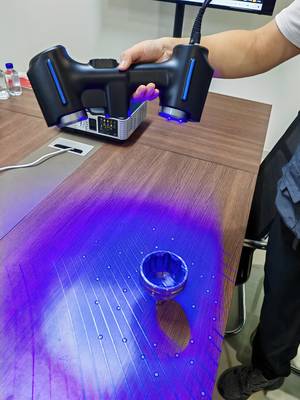
INSVISION’s 3d measuring tool—the Alpha-Projector—replaces these analog methods with metrology-grade 3D laser projection. The system uses binocular machine vision to achieve ±0.25mm positioning accuracy—roughly the thickness of three sheets of paper. Engineers import native CATIA or FiberSIM models directly, and the projector casts green laser contours onto curved surfaces, guiding technicians to exact fastener locations, bracket positions, and trim lines.
The dynamic tracking function distinguishes this 3d measuring tool from static laser systems. If thermal expansion or handling shifts the workpiece, the vision system recalculates and adjusts the projection in real time. No manual realignment. No accumulated error. The result: traceable digital workflows that eliminate the material waste and dimensional drift inherent to physical templates.
Key Capabilities of the Alpha-Projector
| Feature | Description |
|---|---|
| Positioning Accuracy | ±0.25mm (roughly the thickness of three sheets of paper) |
| Model Compatibility | Native CATIA or FiberSIM models |
| Projection Output | Green laser contours for fasteners, brackets, and trim lines |
| Dynamic Tracking | Real-time recalibration if workpiece shifts due to thermal expansion or handling |
First-Time-Right Assembly on Complex Geometries
—
First-Time-Right Assembly on Complex Geometries
Curved composite structures—think aircraft fairings, EV battery enclosures, wind turbine nacelles—present a particular challenge. Traditional scribing methods require skilled technicians to transfer 2D drawings onto 3D surfaces, a process prone to parallax error and interpretation gaps.
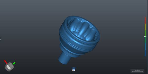
The Alpha-Projector removes this translation layer entirely. By projecting CAD geometry directly onto the actual surface, technicians see exactly where each feature belongs. The system’s compatibility with FiberSIM and CATIA CPD preserves ply orientation data critical for composite layup, ensuring brackets and harnesses align with underlying fiber directions rather than just surface contours.
Field data from tier-one aerospace suppliers shows this approach cuts bracket installation rework from 12% to under 3% on new programs. Training time drops proportionally—operators no longer need to master complex scribing techniques, only interpret laser guidance and confirm placement.
Benefits of Direct CAD-to-Surface Projection
- □ Eliminates parallax error and interpretation gaps from 2D-to-3D translation
- □ Preserves ply orientation data via FiberSIM and CATIA CPD compatibility
- □ Reduces bracket installation rework from 12% to under 3%
- □ Cuts operator training time by simplifying guidance to laser interpretation
Moving Metrology From the Lab to the Line
—
Moving Metrology From the Lab to the Line
Quality assurance traditionally operates downstream: measure, reject, rework, repeat. This inspection-after-failure model consumes resources before problems surface.
INSVISION inverts this paradigm by embedding metrology directly into production. The AlphaVista and X-Track systems provide in-process verification—measuring while building rather than building then measuring. Dynamic tracking maintains projection accuracy without stopping the line for recalibration. When deviations occur, operators see them immediately, before adjacent features compound the error.
This shift from retrospective filtering to real-time correction prevents the cascading delays that plague complex assemblies. For manufacturers facing compressed delivery schedules and penalty clauses, the operational value extends beyond scrap reduction to schedule certainty.
Metrology Integration Workflow
- Embed metrology into production using AlphaVista and X-Track systems
- Perform in-process verification—measuring while building
- Maintain projection accuracy via dynamic tracking without line stoppage
- Detect and correct deviations immediately before errors compound
- Achieve schedule certainty by preventing cascading delays
Preserving Digital Integrity: CAD to Shop Floor
—
Preserving Digital Integrity: CAD to Shop Floor
Data translation remains a hidden friction point in manufacturing. Converting CATIA models to machine-readable formats often strips GD&T annotations, loses coordinate system alignment, or introduces approximation errors that surface only during physical fit checks.
INSVISION eliminates these intermediate steps by ingesting native formats—CATIA, FiberSIM, STEP—without conversion. The 3d measuring tool functions as a direct extension of engineering intent, auto-generating guided operations that preserve design specifications. PTB-certified software ensures measurement traceability meets aerospace and automotive quality standards.
As-built data logging supports regulatory requirements without manual documentation. Multi-source data alignment correlates projected positions with actual achieved dimensions, enabling continuous process improvement rather than merely pass/fail reporting.
Digital Data Handling Comparison
| Traditional Approach | INSVISION Approach |
|---|---|
| Strips GD&T annotations during format conversion | Ingests native CATIA, FiberSIM, STEP without conversion |
| Loses coordinate system alignment | Preserves engineering intent and design specifications |
| Requires manual documentation for compliance | Auto-logs as-built data for regulatory support |
| Relies on pass/fail reporting | Enables continuous process improvement via multi-source data alignment |
Scaling Without Fragmentation
—
Scaling Without Fragmentation
Point solutions create their own problems. A standalone 3d measuring tool that can’t integrate with automated cells or expand to additional stations becomes a bottleneck as volumes grow.
the series’s modular architecture addresses this through a unified software backbone. Manufacturers might start with the portable AlphaScan for low-volume, high-mix operations, then integrate AlphaAutoScan-400 units for automated high-volume lines—all running common software, training protocols, and data formats.
This standardization prevents the vendor fragmentation that drives up total cost of ownership. Engineering teams maintain one competency rather than managing disparate systems. Data flows uninterrupted from design through production to quality records, closing the digital thread that fragmented toolchains often break.
For operations leaders, the calculus is straightforward: replace error-prone manual methods with this precision 3d measuring tool, eliminate the rework cycles that consume 15-25% of assembly labor hours, and build scalable infrastructure that compounds returns as production grows.