Eliminating Manual Layout Errors in Complex Assembly
Eliminating Manual Layout Errors in Complex Assembly
Aerospace and automotive manufacturers still lose hours to chalk lines and physical templates—tools that virtually guarantee rework when tolerances tighten. INSVISION’s 3D messgerät technology, specifically the Alpha-Projector, replaces this legacy approach with CAD-driven green laser projection, eliminating the gap between digital design and shop-floor execution.
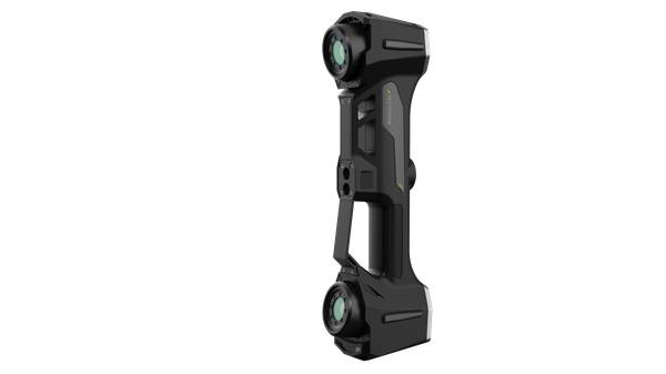
The system centers on a high-precision dual-camera 3D messgerät achieving 0.25mm positioning accuracy. Rather than interpreting drawings, operators see exact part placement projected directly onto the workpiece. Dynamic tracking compensates automatically if the component shifts, maintaining alignment without operator intervention.
The software environment supports FiberSIM and CATIA CPD natively. Engineers generate projection tasks straight from 2D or 3D models through a single interface—no data translation, no manual programming. For manufacturers, this translates to documented rework reductions of up to 70% and assembly workflows that move at production speed rather than inspection speed.
Key System Capabilities
| Feature | Description |
|---|---|
| Positioning Accuracy | 0.25mm with dual-camera 3D messgerät |
| Software Integration | Native support for FiberSIM and CATIA CPD |
| Rework Reduction | Up to 70% documented reduction |
Bringing Metrology-Grade Accuracy to the Shop Floor
Bringing Metrology-Grade Accuracy to the Shop Floor
The traditional compromise—sending parts to a remote CMM lab for traceable measurements—creates bottlenecks that erode throughput. INSVISION’s AlphaVista and AlphaScan systems deploy industrial-grade 3D messgerät hardware directly alongside production equipment, delivering PTB-certified precision of ±0.25 mm without pulling components from the line.
High-precision binocular vision and real-time dynamic tracking maintain measurement integrity even when workpieces move during inspection. Built-in GD&T tools and native CATIA compatibility enable immediate deviation analysis at the point of production. Quality assurance keeps pace with assembly rather than trailing behind it, ensuring ISO/PTB traceability without the logistical overhead of offline metrology.
Shop Floor Metrology Advantages
| Benefit | Detail |
|---|---|
| Precision | PTB-certified ±0.25 mm accuracy |
| Tracking Capability | Real-time dynamic tracking during movement |
| Standards Compliance | ISO/PTB traceability maintained inline |
Flexible Quality Control for High-Mix Production
Flexible Quality Control for High-Mix Production
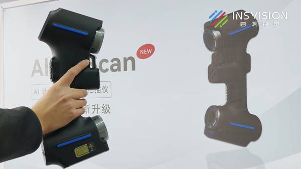
Job shops and contract manufacturers face a different constraint: frequent product changeovers that consume setup time and strain fixed gauging systems. INSVISION addresses this through the X-Track optical tracking system paired with handheld scanners—a 3D messgerät configuration that adapts to part geometry rather than demanding dedicated fixtures.
Advanced dynamic tracking corrects for movement in real time, allowing operators to scan or inspect without rigid clamping. PTB-certified software with integrated GD&T functionality ensures consistent reporting across disparate part families. Support for mainstream 3D formats and direct CAD-driven task creation collapses the path from model import to measurement execution.
The result is measurable: reduced setup times, uninterrupted throughput, and quality data that feeds directly into production planning rather than residing in isolated inspection reports.
High-Mix Production Benefits Checklist
- □ Adaptable 3D messgerät configuration using X-Track and handheld scanners
- □ Real-time movement correction without rigid clamping
- □ PTB-certified software with integrated GD&T for consistent reporting
- □ Direct CAD-driven task creation from mainstream 3D formats
- □ Quality data integrated into production planning
Closing the Design-Build-Verify Loop
Closing the Design-Build-Verify Loop
Digital thread implementation stalls when projection and measurement systems cannot exchange data with engineering environments. INSVISION’s 3D messgerät ecosystem integrates natively with CATIA CPD, FiberSIM, and comparable platforms, enabling engineers to project design intent directly onto physical components and capture as-built deviations without format conversion.
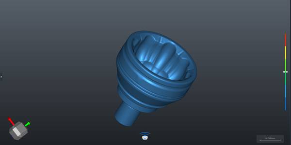
High-precision binocular vision maintains 0.25mm alignment tolerance regardless of workpiece movement. Multi-source data alignment and comprehensive deviation analysis occur within the same PTB-certified environment. Real-world measurements flow back to CAD immediately, accelerating design validation and compressing prototype iteration cycles.
Programmatic guidance eliminates manual interpretation at every stage—projection, assembly, and verification—ensuring that physical output matches digital intent without the accumulation of translation errors that plague conventional workflows.
Digital Thread Integration Steps
- Project design intent directly onto physical components via native CATIA CPD/FiberSIM integration
- Capture as-built deviations without format conversion
- Maintain 0.25mm alignment tolerance using high-precision binocular vision during movement
- Perform multi-source data alignment and deviation analysis in PTB-certified environment
- Feed real-world measurements back to CAD for accelerated validation and iteration