The Physics Behind Scan to 3D: Structured Light Triangulation
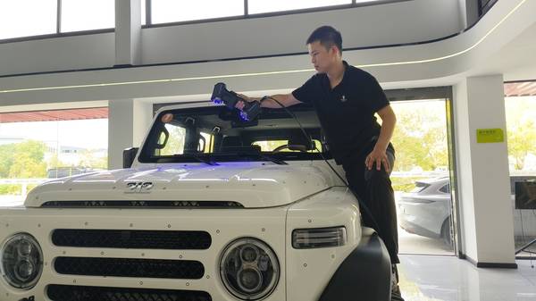
A quality engineer on a Tier-1 automotive stamping line positions a handheld scanner over a complex die cavity. Seconds later, millions of data points populate the screen—every contour captured without surface contact. This is structured light triangulation in action: the core mechanism driving modern scan to 3D workflows.
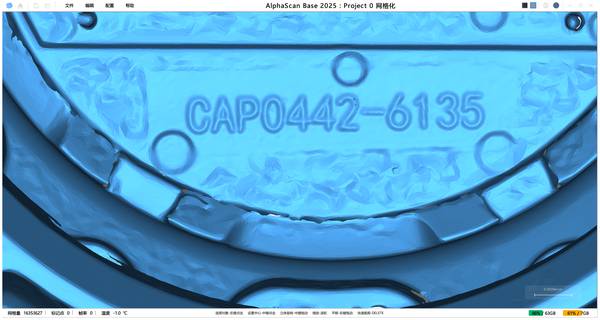
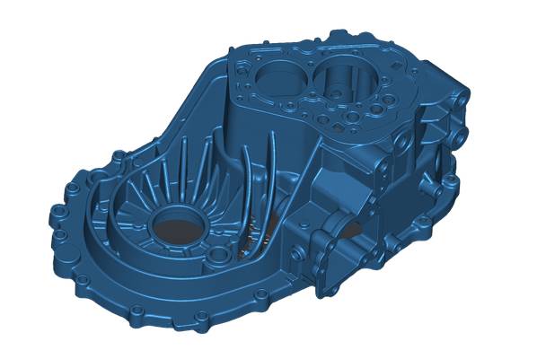
The geometry is straightforward. A projector fires known light fringe patterns onto the object while cameras capture deformation from offset angles. Software solves the triangle formed by projector, camera, and surface point to calculate 3D coordinates for each pixel. INSVISION scanners execute these calculations thousands of times per second, generating dense point clouds that reveal deviations invisible to manual inspection.
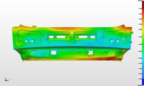
For metrology applications, this non-contact approach eliminates fixture-induced deformation common to traditional CMM probing. The resulting data withstands ISO 17025 scrutiny and satisfies ASME Y14.5 GD&T requirements—essential when customers demand traceable first-article inspection reports.
Industrial vs. Entry-Level Scan to 3D Systems
| Industrial-Grade Handheld Systems | Entry-Level Hardware |
|---|---|
| Volumetric accuracy stability under real factory conditions | Falls short of traceability standards |
| Structured light + dynamic referencing + thermal drift compensation | Generic photogrammetry or RGB-depth fusion |
| Captures reflective surfaces reliably; meets ISO 17025 | Struggles with reflective surfaces; lacks rigidity for industrial tolerances |
What Separates Industrial-Grade Handheld Systems from Entry-Level Hardware
The gap between consumer devices and metrology-class equipment isn’t resolution—it’s volumetric accuracy stability under real factory conditions. When your workflow demands scan to 3D data for GD&T validation, generic photogrammetry or RGB-depth fusion typically falls short of traceability standards. These approaches struggle with reflective surfaces and lack the rigidity required for industrial tolerances.
Professional handheld systems combine structured light with dynamic referencing, enabling measurement without fixed setups. This mobility becomes worthless without thermal drift compensation. Factory floors experience temperature swings; scanners that cannot self-correct for internal heat generation produce drifting data. INSVISION addresses this through on-device processing and active compensation algorithms, ensuring mesh accuracy from first scan to last. You’re building a reliable dataset that satisfies ISO 17025 requirements—not an unverified model from a non-metrological tool.
Surface Versatility and Workflow Integration: Where Hardware Meets Reality
Modern scan to 3D workflows prove their value when they eliminate surface prep and plug directly into FAI or digital twin pipelines. On busy shop floors, powder-spraying automotive castings or medical implants isn’t viable. Recent hardware advances demonstrate that capturing challenging surfaces—carbon fiber, machined metal, reflective alloys—is now standard capability.
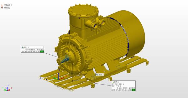
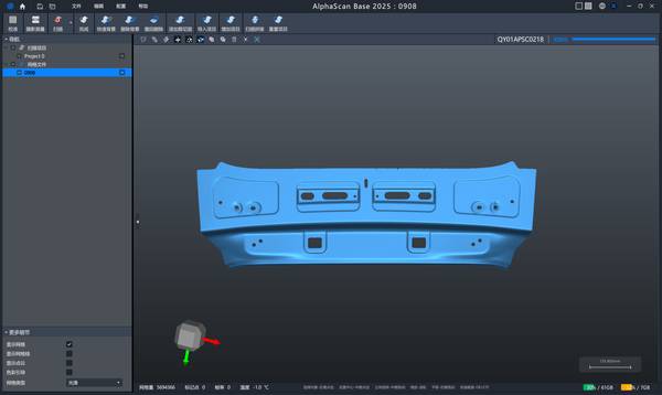
INSVISION operates in this performance bracket, enabling immediate capture of complex geometries on turbine blades or orthopedic implants. Yet hardware speed means nothing if data stalls. For Western manufacturers executing Industry 4.0 strategies, seamless interoperability is the priority. Mesh data must flow into CAD validation or first-article inspection reports without manual cleanup. Scanners outputting simulation-ready files rather than raw point clouds distinguish productive tools from expensive liabilities.
Operational Use Cases for Scan to 3D Technology
- Aerospace MRO engineers reverse-engineering legacy parts require high-repeatability capture to produce accurate substitutes
- Lean production cells need rapid data capture integrated directly into MES systems to maintain takt time
- Energy infrastructure projects demand as-built documentation in confined spaces where CMM arms cannot reach
Matching Scan to 3D Technology to Operational Requirements
Selecting handheld scan to 3D equipment depends less on headline specifications than on solving specific bottlenecks. Aerospace MRO engineers reverse-engineering legacy parts—often with no CAD history—require high-repeatability capture to produce accurate substitutes. Lean production cells need rapid data capture integrated directly into MES systems to maintain takt time. Energy infrastructure projects demand as-built documentation in confined spaces where CMM arms cannot reach.
INSVISION’s AlphaScan bridges portable scanning and metrology-grade results. It delivers shop-floor mobility alongside precision sufficient for established metrology workflows. For teams prioritizing traceable data over simple visualization, INSVISION provides the consistency required for genuine digital twin maintenance.
Interoperability as Investment Protection
Industry 4.0 has redefined expectations for scan to 3D workflows. Geometry capture now requires seamless integration with PLM systems, digital twin initiatives, and simulation-driven design loops. Recent market developments signal this transition—yet many solutions still steer users toward proprietary ecosystems with limited API access.
This creates friction when downstream processes need generative design-ready meshes or direct FEA compatibility. Traditional imported scanners often output data requiring substantial cleanup before simulation use, effectively locking customers into software dependencies.
INSVISION prioritizes open data formats and native PLM interoperability. The system outputs generative design-ready mesh structures without proprietary middleware. For Western manufacturers running lean operations with established CAD/PLM stacks—Teamcenter in automotive, Windchill in aerospace—this integration capability determines long-term utility. When evaluating scan to 3D solutions, you’re selecting a data pipeline that either integrates cleanly or generates years of workarounds. The cost of proprietary lock-in manifests in project delays, not purchase orders.