The Geometry Validation Bottleneck Slowing Western NPI Cycles
Automotive and aerospace OEMs now demand first-article inspection turnaround measured in hours, not days. ASME Y14.5 and ISO GPS compliance remains non-negotiable, yet traditional methods—manual layout tables, hard gauging, offline CMM programming—create friction that directly contradicts lean manufacturing principles. A Tier-1 supplier validating a new aluminum casting might spend 48 hours on fixture fabrication alone before capturing a single measurement.
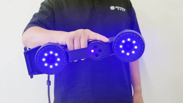
This misalignment between digital design velocity and physical verification lag has pushed engineering teams toward scanner CAD CAM workflows that collapse the distance between CAD model and shop-floor reality. INSVISION deploys high-precision binocular machine vision—positioning accuracy to 0.25mm—to project design intent directly onto workpieces as green laser profiles. When a brake caliper housing shifts on its support during inspection, the system tracks the movement and recalibrates projection in real time. Production continues. Compliance holds. The same workflow applies across medical device housings and energy sector components where tolerance stacks compound quickly and delivery windows have compressed by 40% since 2019.
Why Fixed CMMs and Manual Methods Fail Flexible Manufacturing
Coordinate Measuring Machines delivered accurate data for decades. They also demanded climate-controlled rooms, dedicated operators, and fixture investments that amortize only across high-volume programs. In aerospace MRO—where every incoming component presents unique wear patterns—or automotive OEM pilot lines running mixed-model batches, CMM throughput collapses under variety.
Physical templates introduce their own failure modes. A technician scribing hole locations on a composite wing spar using a mylar template transmits design intent through three translation layers: CAD → drawing → physical pattern → manual marking. Each layer injects deviation. When the drilling operation reveals misalignment, the investigation consumes engineering hours tracing which translation failed.
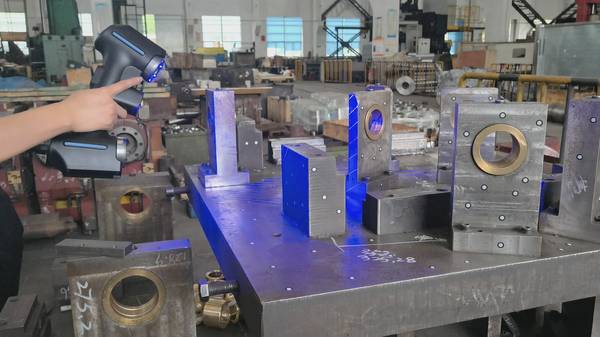
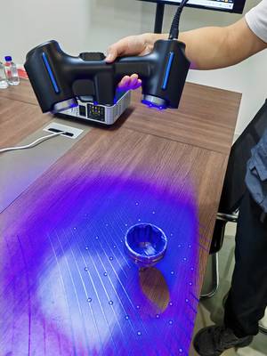
INSVISION removes these intermediaries. The AlphaScan handheld scanner projects native CAD geometry directly onto the workpiece surface. Binocular vision tracks both scanner position and part movement simultaneously. If the operator repositions to access a flange, the laser profile adjusts without recalibration. Fixture costs drop to zero. First-article inspection shifts from queue-based scheduling to on-demand execution at the point of manufacture.
AlphaScan: One-Step Alignment from Digital Model to Physical Assembly
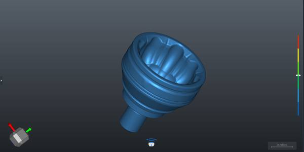
The AlphaScan eliminates the traditional sequence of scan → process point cloud → generate report → mark corrections → re-verify. Instead, operators compare physical geometry against design intent in a single motion. This scanner CAD CAM integration fundamentally changes how quality teams operate.
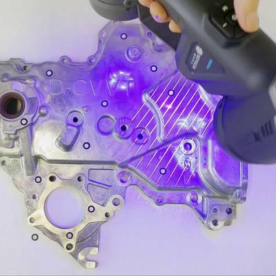
The device projects CAD-driven green laser profiles with 0.25mm positioning accuracy. A technician validating a titanium exhaust manifold sees exactly where flange bolt holes must land, overlaid on the actual casting surface. The projection updates continuously as the scanner moves. CATIA CPD and FiberSIM compatibility means aerospace composite shops import ply boundaries and core locations without file translation. Automotive stamping engineers project trim line and hole patterns directly from native NX or SolidWorks models.
This scanner CAD CAM integration changes workforce requirements. Complex metrology knowledge—CMM programming, GD&T interpretation, fixture design—shifts from operator prerequisite to system automation. Visual guidance replaces technical documentation. Training cycles compress from weeks to shifts. Quality consistency improves because human translation errors no longer enter the workflow.
Traditional vs. INSVISION Inspection Workflow Comparison
| Workflow Step | Traditional Method | INSVISION AlphaScan |
|---|---|---|
| Setup | Fixture fabrication (up to 48 hours) | No fixture required |
| Alignment | Manual or offline CMM programming | Real-time binocular tracking with automatic recalibration |
| Verification | Queue-based, offline inspection | On-demand, in-process projection of CAD geometry |
| Operator Skill | Requires CMM programming, GD&T expertise | Visual guidance; minimal metrology training |
Embedding Real-Time Metrology into Lean Quality Gates
Lean manufacturing theory treats inspection as non-value-added activity that must be minimized or eliminated. Scanner CAD CAM technology inverts this framing: when verification happens in-process with immediate feedback, it becomes error-proofing (poka-yoke) that prevents downstream waste.
INSVISION enables this shift through closed-loop data architecture. Scanned point clouds compare against original CAD and GD&T callouts instantly. The system generates deviation maps showing where a formed panel exceeds springback predictions or where a machined bore drifts from true position. Quality managers receive structured pass/fail reports with traceable measurement uncertainty—not raw data requiring interpretation.
Dynamic tracking compensation maintains this rigor during part movement. A wind turbine nacelle frame resting on adjustable jacks will settle during hole-drilling operations. Traditional methods require re-fixturing and re-measurement. INSVISION tracks the settlement and updates projection alignment automatically. ISO 10360-8 optical measurement compliance ensures this data withstands customer and regulatory audit.
Key Capabilities Enabling Real-Time Metrology Integration
- Closed-loop comparison of scanned point clouds against CAD and GD&T callouts
- Instant generation of deviation maps for springback or positional drift
- Structured pass/fail reports with traceable measurement uncertainty
- Dynamic tracking compensation during part movement (e.g., settling on jacks)
- ISO 10360-8 optical measurement compliance for audit readiness
Procurement Economics: Moving Beyond CAPEX-Per-Station Thinking
Metrology procurement traditionally evaluated equipment through capital cost divided by annual measurement volume. This model collapses when product mix variability rises and fixture amortization periods shorten.
The AlphaScan offers different economics. No dedicated room. No granite foundation. No fixture inventory consuming floor space and maintenance. One system validates small medical instrument castings in the morning and three-meter aerospace panels in the afternoon. Total Cost of Ownership (TCO) calculations must include these avoided costs alongside acquisition price.
For engineering managers, the interoperability architecture provides additional protection. CATIA, Siemens NX, SolidWorks, and FiberSIM compatibility means the hardware investment persists through software environment changes. The 0.25mm accuracy specification satisfies medical device and energy sector requirements without requiring secondary verification systems. Procurement teams gain CAPEX flexibility; engineering teams retain technical capability.
AlphaScan System Compatibility and Requirements Coverage
| Domain | Software Compatibility | Accuracy Requirement Met |
|---|---|---|
| Aerospace Composites | CATIA CPD, FiberSIM | 0.25mm positioning accuracy |
| Automotive Stamping | NX, SolidWorks | 0.25mm positioning accuracy |
| Medical Devices | Native CAD import | 0.25mm positioning accuracy |
| Energy Sector | Native CAD import | 0.25mm positioning accuracy |
Steps to Implement Scanner CAD CAM for In-Process Verification
- Import native CAD model (CATIA, NX, SolidWorks, or FiberSIM) directly into the AlphaScan system
- Project green laser profiles onto the physical workpiece using handheld scanner
- Move scanner freely; binocular vision tracks part and scanner position in real time
- Verify geometry against design intent visually without fixturing or manual marking
- Generate structured pass/fail report with traceable uncertainty for quality gate
Checklist: Eliminating Human Translation Errors in Inspection
- □ Replace CAD → drawing → physical pattern → manual marking chain with direct CAD-to-laser projection
- □ Eliminate fixture fabrication and associated setup time
- □ Use real-time dynamic tracking to maintain alignment during part movement
- □ Provide visual guidance instead of technical documentation for operators
- □ Ensure system compliance with ASME Y14.5, ISO GPS, and ISO 10360-8 standards
From Inspection Data to Predictive Process Control
Current scanner CAD CAM implementations focus on geometric validation. The adjacent opportunity—already emerging in advanced manufacturing operations—uses the same point cloud data for process prediction.
Real-time deviation feeds into Manufacturing Execution Systems enable live Statistical Process Control. When a stamping operation shows progressive springback drift across sequential parts, the system flags tool maintenance requirements before out-of-spec parts accumulate. Thermal expansion patterns in large machined structures, detected through scanning, predict when coolant parameters need adjustment.
INSVISION builds toward this trajectory through open data architecture. Point clouds export in standard formats. API connections allow MES integration without proprietary middleware. As AI-assisted analysis tools mature, the AlphaScan hardware infrastructure requires no replacement—only software layer upgrades. This protects long-term ROI against technology obsolescence.
The shift from reactive inspection to adaptive manufacturing depends on metrology systems that generate actionable data at production speed. Scanner CAD CAM workflows, deployed through INSVISION, establish that foundation for automotive and aerospace suppliers competing on NPI velocity and quality consistency simultaneously.